


Product Catalog
Bottom Tank Sampler
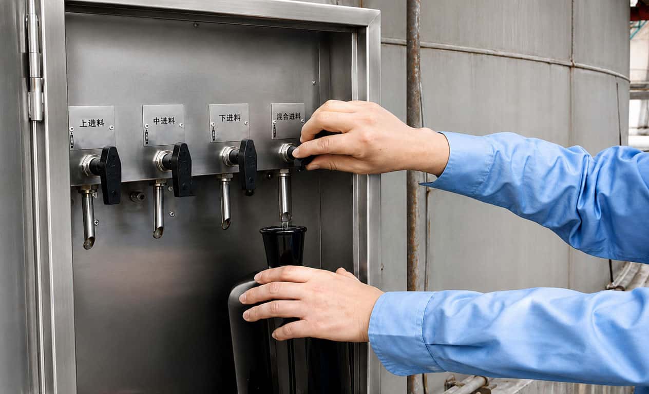
The Under-Tank Sampler is a storage tank liquid sampling device designed in accordance with GB/T 4756-1998 Method for Manual Sampling of Petroleum Liquids. Operators do not need to climb the tank; upper, middle, lower, bottom and composite samples can all be collected underneath the tank, featuring high safety, high efficiency, precise sampling and fully enclosed structure.
- Parameters
- Drawing
- Application areas
Structural Composition
In-tank Components:Upper / middle / lower sampling pipes, float ball / float cylinder, proportional telescopic support, tank bottom support base, 304 stainless steel metal hose.
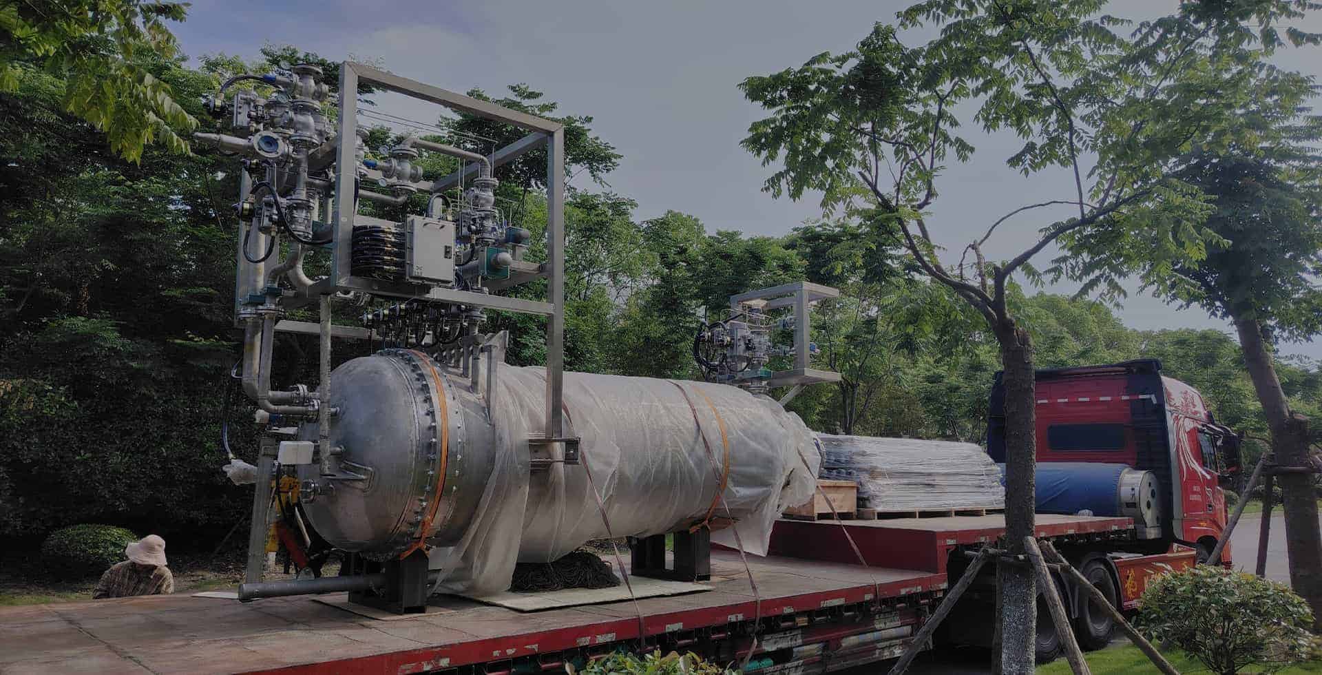
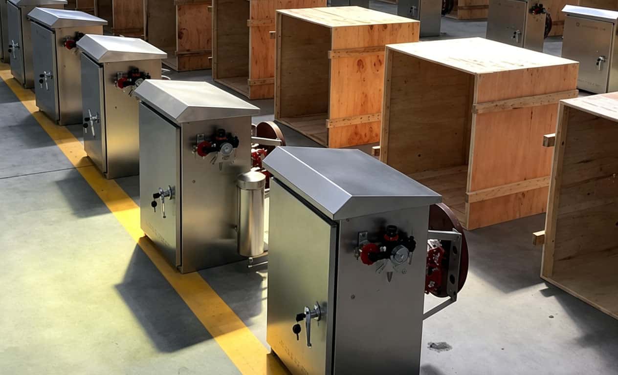
External Tank Components:Weatherproof & dustproof operation cabinet (equipped with manual / pneumatic pump, multi-position diverter valve, sampling valve, emergency shut-off valve), connecting flanges and pipelines.
Working Principle
The top of the telescopic frame is connected to the float ball, and its bottom is fixed to the tank base. It moves along with liquid level fluctuation to adjust the position of sampling pipes, keeping sampling ports stably at 1/6 liquid level (upper layer), 1/2 liquid level (middle layer), 5/6 liquid level (lower layer), or 200 mm above tank bottom. Samples are delivered to the external operation cabinet via independent pipelines, enabling single-point sampling or proportional composite sampling.
Applicable Standards
GB/T 4756-2015, Method for Manual Sampling of Petroleum Liquids
Main Features
Safe Tank-free Operation: No tank climbing required even under harsh weather; enclosed sampling reduces risks of toxic medium exposure and static electricity.
Precise Positioning: Sampling point deviation ≤ ±20 mm, fully compliant with national standard.
Versatile Functions: Supports single-point sampling and proportional composite sampling; manual or pneumatic drive optional.
Labor-saving Operation: Effortless hand cranking, one operator can complete sampling rapidly.
Compact Structure: Wall-mounted or movable installation, easy inspection and maintenance.
Structure & Connection Parameters
Process inlet: DN15/DN20/DN25, available with flanges complying with GB, HG, ANSI, DIN, GOST standards or ferrule fitting connections.
Parameter
| Parameter | Value / Description |
|---|---|
| Applicable Standards | GB/T 4756-1998、SH/T 3414-1999 |
| Sampling Points | Upper (1/6 liquid level), Middle (1/2 liquid level), Lower (5/6 liquid level), Bottom (200 mm above tank floor), Composite sample (1:1:1 ratio) |
| Sampling Precision | Positioning error ≤ ±20 mm, composite sample precision ≤ ±1% |
| Design Pressure | PN1.0–2.5MPa |
| Temperature Range | -15℃ ~ 90℃ (heat tracing optional) |
| Materials | Medium-wetted parts: 304 / 316 stainless steel; Operation cabinet: 304 stainless steel; Hose: 304 metal flexible hose |
| Sampling Pipe Nominal Diameter | DN10–15mm(≤20mm) |
| Driving Modes | Manual (hand crank pump), Pneumatic (0.4–0.6 MPa), Explosion-proof electric drive |
| Cabinet Protection Class | IP54, rainproof, dustproof, anti-theft |
| Applicable Tank Volume | 100–50000m³ |
| All data above are for reference only. Please contact us for detailed parameters. | |


Previous: Hand-crank Sampler Next: Pipeline Sampling Valve